Rozwiązania ADKSolid
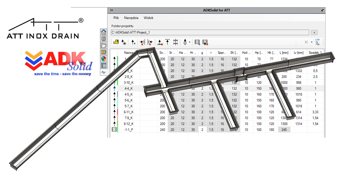
ADKSolid for ATT
Dodatek ADKSolid for ATT dostarcza szeregu funkcjonalności, które umożliwiają skrócenie czasu przygotowania konstrukcji sieci kanałów odwodnieniowych w systemie 3D CAD SOLIDWORKS®.
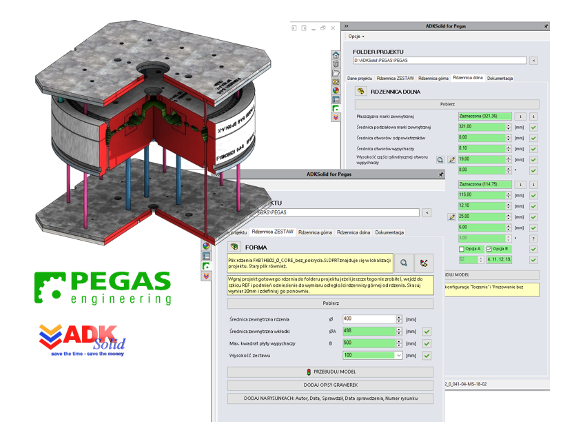
ADKSolid for PEGAS
Dodatek ADKSolid for PEGAS to zintegrowane z systemem 3D CAD SOLIDWORKS® oprogramowanie na zamówienie firmy P.P.H.U. Pegas S.c. J. Gąsior, J.P.P. Paulukiewicz, którego zadaniem jest zautomatyzowanie prac projektowych związanych z przygotowaniem modelu 3D CAD oraz dokumentacji płaskiej oprzyrządowania technologicznego (formy) do wytwarzania rdzeni odlewniczych tarcz hamulcowych.
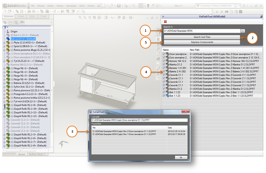
FixPathTool
FixPathTool – makro, którego zadaniem jest odnalezienie "zagubionych" komponentów we wskazanej lokalizacji przestrzeni dyskowej, a następnie zbiorcze ich "zastąpienie". Możesz z poziomu Windows zmieniać nazwy folderów, przenosić pliki SOLIDWORKS® w dowolne miejsce nie martwiąc się o projekt w SOLIDWORKS®. Z narzędziem FixPathTool strukturę plików złożenia odbudujesz błyskawicznie.
SaveAsSolid
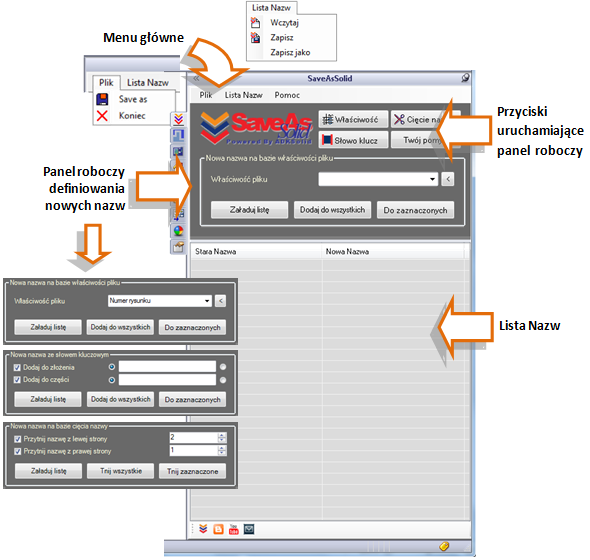 SaveAsSolid - dodatek/makro automatyzujące proces zapisu złożenia z nowymi, zaproponowanymi przez Użytkownika nazwami plików.
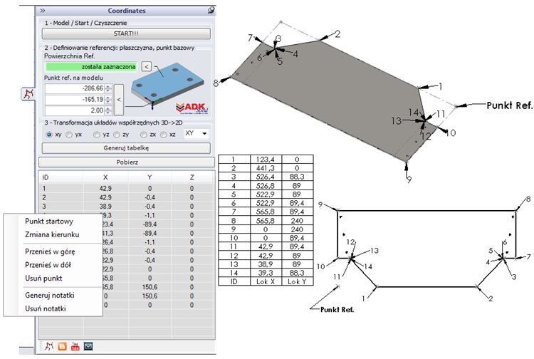
Coordinates
Coordinates - to dodatek, który umożliwia pobranie współrzędnych punktów wybranej ściany względem punktu bazowego.
SheetSolid
Dodatek SheetSolid skierowany jest do konstruktorów i technologów, którzy wykorzystują system SOLIDWORKS® do projektowania części z blachy. Dodatek umożliwia pobieranie z modelu złożenia niezbędnych informacji produkcyjnych o częściach z blachy, ich edycję i archiwizację oraz umożliwia zautomatyzowane generowanie dokumentacji przeznaczonej dla działu produkcji m.in. plików DXF oraz dokumentów wypisu formatek w formacie MS Excel®.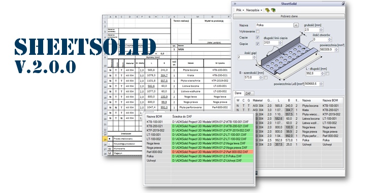
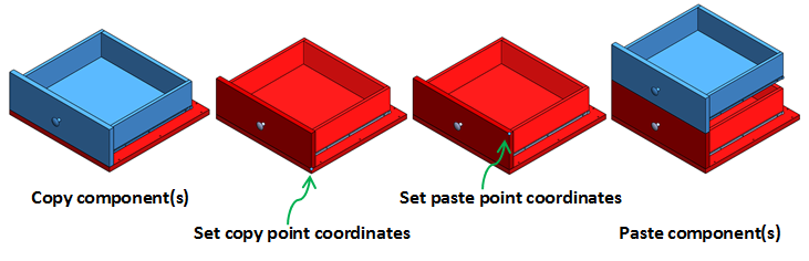
Component Manipulator
Component Manipulator – dodatek, który wzbogaca funkcjonalność SOLIDWORKS® o możliwość kopiowania i wklejania komponentów względem punktu referencyjnego oraz pozwala na szybkie przemieszczanie w przestrzeni zaznaczonych komponentów o zdefiniowaną odległość wzdłuż osi X, Y i Z.
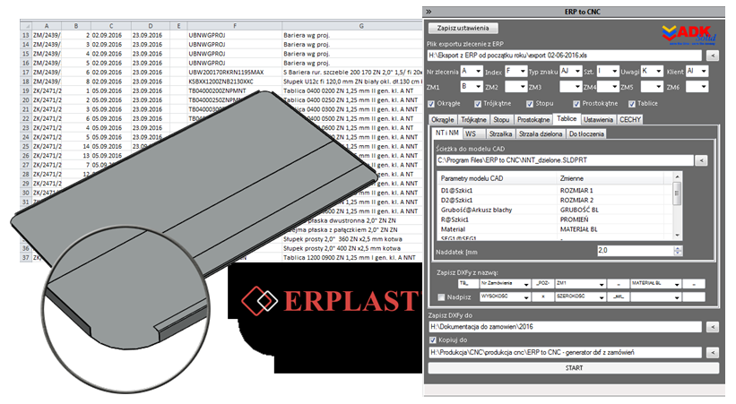
ERP to CNC
ERP to CNC to zintegrowany z SOLIDWORKS® dodatek, który został zaprojektowany i oprogramowany przez firmę ADKSolid na zamówienie firmy ERPLAST. Po wskazaniu pliku exportu z systemu ERP, przechowującego specyfikację zamówienia dotyczącego znaków drogowych, dodatek generuje niezbędne pliki DXF i zapisuje je z odpowiednią nazwą we wskazanej lokalizacji przestrzeni dyskowej.